Achieving Cloud to Cloud Connectivity

Enabling Layer 3 Connections between Different Cloud Environments
PREREQUISITES
- An existing (Active) Virtual Router.
- Understand how you would like to set up your IP space.
- Cloud Provider 1 Subnet.
- Cloud Provider 2 Subnet.
To enable connectivity between cloud providers, follow the steps outlined below:
Step 1: | Create a Layer 3 EVC to the first cloud service provider. |
Step 2: | Create a Layer 3 EVC to the second cloud service provider. |
Step 3: | Tie your networks together using Dynamic Routing. |
EXAMPLE USE CASE
This example will provide a walkthrough of how to enable cloud to cloud connectivity between AWS and Microsoft Azure. We will assume that AWS is the first cloud provider and Microsoft Azure as the second (Secondary) cloud provider.
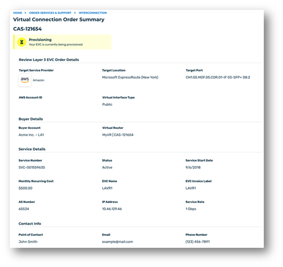
STEP 1: CREATE A LAYER 3 EVC BETWEEN YOUR VR AND AWS
Follow the detailed steps located in the section of this document titled “Creating a Layer 3 connection to AWS”. Once all steps are completed, automated provisioning will take place to build your EVC to AWS. Upon successful automated provisioning, your EVC will show an “Active” status.
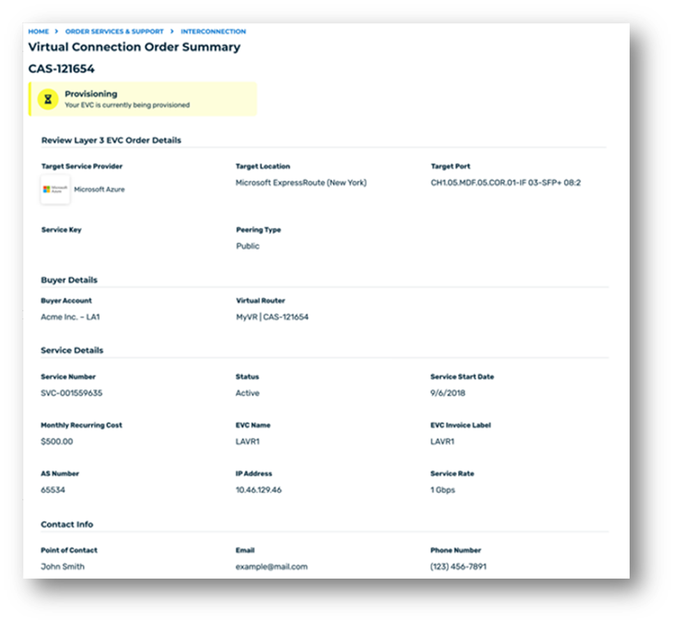
STEP 2: CREATE A LAYER 3 EVC BETWEEN YOUR VR AND MICROSOFT AZURE
Follow the detailed steps located in the section of this document titled “Creating a Layer 3 connection to Azure”. Once all steps are completed, automated provisioning will take place to build your EVC to Azure. Upon successful automated provisioning, your EVC will show an “Active” status.
STEP 3: SET UP DYNAMIC ROUTING TABLES TO ALLOW COMMUNICATION BETWEEN CLOUD ENVIRONMENTS
This step in the process outlines the necessary steps that need to be taken for traffic to flow from one cloud environment to another.
- Navigate to the OCX Dashboard and locate the EVC inventory screen.
- Select the EVC in which you wish to enable cloud to cloud connectivity and click the hyperlinked service number.
- Click the “Routing Policies” tab.
- To add a new prefix, click the “Add New Prefix” button. To modify an existing entry, locate the prefix and click the “Edit” button.
- A modal window will appear for users to make changes to their routing table.
- In the policy field, select “Import” and enter the subnet associated to the first cloud environment:
- For this example, we are enabling connectivity between an AWS (1) and Microsoft Azure (2) cloud environment. This step requires users to provide the AWS subnet. The policy type to apply should be set an import policy.
- Select the network range.
- Click the “+” button to have another row generated.
- In the policy field, select “Export” and enter the subnet associated to the secondary Cloud environment:
- For this example, we are enabling connectivity between an AWS (1) and Microsoft Azure (2) cloud environment. This step requires users to provide the Azure subnet. The policy type to apply should be an export policy.
NOTE: For Steps 5 to 9, see image below.
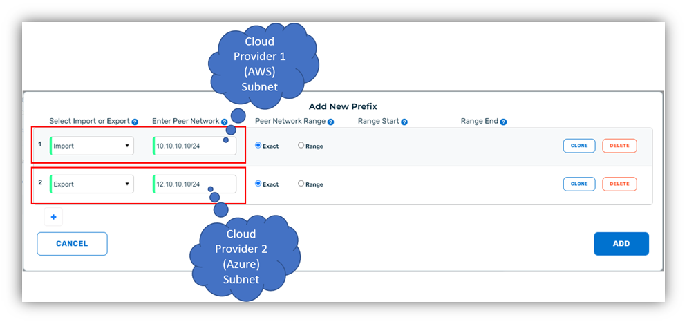
- Click the “Add” button. Once the “Add” button is clicked, the information will be saved and applied to your EVC.
- Repeat Steps 1 –to10 for the Microsoft Azure EVC (or secondary EVC). Steps 1 to 10 must be completed for the secondary cloud provider EVC to complete the routing table between both cloud environments.
- After all steps are complete for both EVCs, the process will be complete and the two cloud environments can begin exchanging traffic.
NOTE: Setting up routing policies for your prefixes can be done at the time of EVC creation or after users have submitted their EVC requests.